| General specifications | ||
|---|---|---|
| Signal type | Analog input | |
| Functional safety related parameters | ||
| Safety Integrity Level (SIL) | SIL 2 | |
| Systematic capability (SC) | SC 3 | |
| Supply | ||
| Connection | Power Rail or terminals 9+, 10- | |
| Rated voltage | 19 … 30 V DC | |
| Ripple | ≤ 10 % | |
| Rated current | ≤ 45 mA at 24 V and 20 mA source mode output | |
| Power dissipation | ≤ 800 mW | |
| Power consumption | ≤ 1.1 W | |
| Input | ||
| Connection side | field side | |
| Connection | terminals 1+, 2-; 3+, 4- | |
| Input signal | 4 … 20 mA limited to approx. 26 mA | |
| Open circuit voltage/short-circuit current | terminals 1+, 2-: 22 V / 26 mA | |
| Voltage drop | terminals 3+, 4- : approx. 5 V | |
| Available voltage | terminals 1+, 2-: ≥ 15 V at 20 mA ; ≥ 18 V at 4 mA | |
| Output | ||
| Connection side | control side | |
| Connection | terminals 5-, 6+ terminals 5-, 8+ for HART resistor |
|
| Load | 0 … 350 Ω (source mode) | |
| Output signal | 4 … 20 mA or 1 … 5 V (on 250 Ω, 0.1 % internal shunt) 4 … 20 mA (sink mode), operating voltage 10 … 30 V |
|
| Ripple | 20 mV rms | |
| Transfer characteristics | ||
| Deviation | at 20 °C (68 °F) < 0.1 % of full scale, incl. non-linearity and hysteresis (source mode and sink mode 4 … 20 mA) ≤ ± 0.2 % incl. non-linearity and hysteresis (source mode 1 … 5 V) |
|
| Influence of ambient temperature | < 2 µA/K (-20 … 70 °C (-4 … 158 °F)); < 4 µA/K (-40 … -20 °C (-40 … -4 °F)) (source mode and sink mode 4 … 20mA) < 0.5 mV/K (-20 … 70 °C (-4 … 158 °F)); < 1 mV/K (-40 … -20 °C (-40 … -4 °F)) (source mode 1…5 V) |
|
| Frequency range | field side into the control side: bandwidth with 0.5 Vpp signal 0 … 3 kHz (-3 dB) control side into the field side: bandwidth with 0.5 Vpp signal 0 … 3 kHz (-3 dB) |
|
| Settling time | ≤ 50 ms | |
| Rise time/fall time | ≤ 10 ms | |
| Galvanic isolation | ||
| Input/Output | basic insulation according to IEC/EN 61010-1, rated insulation voltage 300 Veff | |
| Input/power supply | reinforced insulation according to IEC/EN 61010-1, rated insulation voltage 300 Veff | |
| Output/power supply | basic insulation according to IEC/EN 61010-1, rated insulation voltage 300 Veff | |
| Indicators/settings | ||
| Display elements | LED | |
| Control elements | DIP switch | |
| Configuration | via DIP switches | |
| Labeling | space for labeling at the front | |
| Directive conformity | ||
| Electromagnetic compatibility | ||
| Directive 2014/30/EU | EN 61326-1:2013 (industrial locations) | |
| Conformity | ||
| Electromagnetic compatibility | NE 21:2017 EN 61326-3-2:2018 |
|
| Degree of protection | IEC 60529:2001 | |
| Protection against electrical shock | UL 61010-1:2012 | |
| Ambient conditions | ||
| Ambient temperature | -40 … 70 °C (-40 … 158 °F) | |
| Mechanical specifications | ||
| Degree of protection | IP20 | |
| Connection | screw terminals | |
| Mass | approx. 100 g | |
| Dimensions | 12.5 x 114 x 124 mm (0.5 x 4.5 x 4.9 inch) , housing type A2 | |
| Mounting | on 35 mm DIN mounting rail acc. to EN 60715:2001 | |
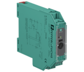
KCD2-STC-EX1
Ex-erotin analogiatuloviesteille
- 1-kanavainen galvaaninen erotin
- 24 VDC jännitesyöttö (Power Rail)
- Tulo Hart-viestin läpäisevä
- Lähtö 4-20mA tai 1-5V
- Johdinkatkoksen valvonta
- Kotelon leveys 12.5 mm
- SIL 2