| General specifications | ||
|---|---|---|
| Signal type | Digital Input | |
| Functional safety related parameters | ||
| Safety Integrity Level (SIL) | SIL 2 | |
| Systematic capability (SC) | SC 3 | |
| Supply | ||
| Connection | terminals 14, 15 | |
| Rated voltage | 19 … 30 V DC / 90 … 253 V AC 50 … 60 Hz | |
| Power dissipation/power consumption | ≤ 1 W / ≤ 1 W ; 3 VA | |
| Input | ||
| Connection side | field side | |
| Connection | terminals 1+, 2+, 3- | |
| Rated values | acc. to EN 60947-5-6 (NAMUR) | |
| Open circuit voltage/short-circuit current | approx. 8 V DC / approx. 8 mA | |
| Switching point/switching hysteresis | 1.2 … 2.1 mA / approx. 0.2 mA | |
| Line fault detection | breakage I ≤ 0.1 mA , short-circuit I > 6 mA | |
| Pulse/Pause ratio | min. 20 ms / min. 20 ms | |
| Output | ||
| Connection side | control side | |
| Connection | terminals 7, 8, 9 | |
| Output | signal ; relay | |
| Contact loading | 250 V AC/2 A/cos φ > 0.75; 126.5 V AC/4 A/cos φ > 0.75; 40 V DC/2 A resistive load | |
| Minimum switch current | 2 mA / 24 V DC | |
| Energized/De-energized delay | approx. 20 ms / approx. 20 ms | |
| Mechanical life | 107 switching cycles | |
| Transfer characteristics | ||
| Switching frequency | < 10 Hz | |
| Galvanic isolation | ||
| Input/Output | reinforced insulation according to IEC/EN 61010-1, rated insulation voltage 300 Veff | |
| Input/power supply | reinforced insulation according to IEC/EN 61010-1, rated insulation voltage 300 Veff | |
| Output/power supply | reinforced insulation according to IEC/EN 61010-1, rated insulation voltage 300 Veff | |
| Indicators/settings | ||
| Display elements | LEDs | |
| Control elements | DIP switch | |
| Configuration | via DIP switches | |
| Labeling | space for labeling at the front | |
| Directive conformity | ||
| Electromagnetic compatibility | ||
| Directive 2014/30/EU | EN 61326-1:2013 (industrial locations) | |
| Low voltage | ||
| Directive 2014/35/EU | EN 61010-1:2010+A1:2019+A1:2019/AC:2019 | |
| Conformity | ||
| Electromagnetic compatibility | NE 21:2017 , EN 61326-3-1:2017 , EN IEC 61326-3-2:2018 , EN IEC 61326-1:2021 (industrial locations) | |
| Degree of protection | IEC 60529:1989+A1:1999+A2:2013 | |
| Input | EN 60947-5-6:2000 | |
| Ambient conditions | ||
| Ambient temperature | -40 … 60 °C (-40 … 140 °F) extended ambient temperature range up to 70 °C (158 °F), refer to manual for necessary mounting conditions |
|
| Mechanical specifications | ||
| Degree of protection | IP20 | |
| Connection | screw terminals | |
| Mass | approx. 150 g | |
| Dimensions | 20 x 119 x 115 mm (0.8 x 4.7 x 4.5 inch) (W x H x D) , housing type B2 | |
| Height | 119 mm | |
| Width | 20 mm | |
| Depth | 115 mm | |
| Mounting | on 35 mm DIN mounting rail acc. to EN 60715:2001 | |
| Data for application in connection with hazardous areas | ||
| EU-type examination certificate | FIDI 22 ATEX 0029 X | |
| Marking |  II 3(1)G Ex ec nC [ia Ga] IIC T4 Gc II 3(1)G Ex ec nC [ia Ga] IIC T4 Gc II (1)D [Ex ia Da] IIIC II (1)D [Ex ia Da] IIIC I (M1) [Ex ia Ma] I I (M1) [Ex ia Ma] I |
|
| Input | Ex ia | |
| Voltage | 10.5 V | |
| Current | 13 mA | |
| Power | 34 mW (linear characteristic) | |
| Supply | ||
| Maximum safe voltage | 253 V AC (Attention! Um is no rated voltage.) | |
| Output | ||
| Maximum safe voltage | 253 V AC (Attention! The rated voltage can be lower.) | |
| Galvanic isolation | ||
| Input/Output | safe electrical isolation acc. to IEC/EN 60079-11, voltage peak value 375 V | |
| Input/power supply | safe electrical isolation acc. to IEC/EN 60079-11, voltage peak value 375 V | |
| Directive conformity | ||
| Directive 2014/34/EU | EN IEC 60079-0:2018 , EN 60079-7:2015+A1:2018 , EN 60079-11:2012 , EN IEC 60079-15:2019 |
|
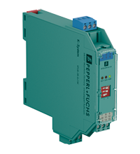
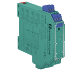
KFU8-SR-Ex1.W
Ex-erotin kytkintuloille
(korvaa tuotteen KFA6-SR2-EX1.W)
- 1-kanavainen galvaaninen erotin
- Jännite 19 … 30 V DC / 90 … 253 V AC 50 … 60 Hz
- Kytkin- tai Namuranturitulo
- Relelähtö
- Johdinkatkoksen valvonta
- Kotelon leveys 20 mm
- SIL 2

