| General specifications | ||
|---|---|---|
| Signal type | Analog input | |
| Functional safety related parameters | ||
| Safety Integrity Level (SIL) | SIL 2 | |
| Supply | ||
| Connection | Power Rail or terminals 14+, 15- | |
| Rated voltage | 18 … 30 V DC | |
| Ripple | within the supply tolerance | |
| Power dissipation | ≤ 1 W at maximum load | |
| Power consumption | ≤ 1.6 W at maximum load | |
| Input | ||
| Connection side | field side | |
| Connection | terminals 1+, 2-, 3 | |
| Input signal | 0/4 … 20 mA | |
| Open circuit voltage/short-circuit current | terminals 1+, 3: 23 V / 25 mA | |
| Input resistance | max. 265 Ω terminals 2-, 3 , max. 330 Ω terminals 1+, 3 | |
| Available voltage | ≥ 16 V at 20 mA ; ≥ 20 V at 4 mA , terminals 1+, 3 | |
| Output | ||
| Connection side | control side | |
| Connection | terminals 7+, 8-, 9- (sink) terminals 7-, 8+, 9+ (source) see additional information |
|
| Load | 0 … 800 Ω | |
| Output signal | 0/4 … 20 mA (overload > 25 mA) | |
| Ripple | max. 50 µA rms | |
| External supply (loop) | 2 … 30 V DC | |
| Transfer characteristics | ||
| Deviation | at 20 °C (68 °F), 0/4 … 20 mA ≤ 10 µA incl. calibration, linearity, hysteresis, loads and fluctuations of supply voltage |
|
| Influence of ambient temperature | ≤ 0.25 µA/K | |
| Frequency range | field side into the control side: bandwidth with 0.5 Vpp signal 0 … 7.5 kHz (-3 dB) control side into the field side: bandwidth with 0.5 Vpp signal 0.3 … 7.5 kHz (-3 dB) |
|
| Settling time | 200 µs | |
| Rise time/fall time | 100 µs | |
| Galvanic isolation | ||
| Output/power supply | functional insulation, rated insulation voltage 50 V AC | |
| Indicators/settings | ||
| Display elements | LED | |
| Labeling | space for labeling at the front | |
| Directive conformity | ||
| Electromagnetic compatibility | ||
| Directive 2014/30/EU | EN 61326-1:2013 (industrial locations) | |
| Conformity | ||
| Electromagnetic compatibility | NE 21:2012 EN 61326-3-2:2008 |
|
| Degree of protection | IEC 60529:2001 | |
| Protection against electrical shock | UL 61010-1:2012 | |
| Ambient conditions | ||
| Ambient temperature | -20 … 70 °C (-4 … 158 °F) | |
| Mechanical specifications | ||
| Degree of protection | IP20 | |
| Connection | screw terminals | |
| Mass | approx. 150 g | |
| Dimensions | 20 x 124 x 115 mm (0.8 x 4.9 x 4.5 inch) (W x H x D) , housing type B2 | |
| Mounting | on 35 mm DIN mounting rail acc. to EN 60715:2001 | |
| Data for application in connection with hazardous areas | ||
| EU-type examination certificate | CML 17 ATEX 2029X | |
| Marking |  II (1)G [Ex ia Ga] IIC II (1)D [Ex ia Da] IIIC I (M1) [Ex ia Ma] I II (1)G [Ex ia Ga] IIC II (1)D [Ex ia Da] IIIC I (M1) [Ex ia Ma] I |
|
| Input | [Ex ia Ga] IIC, [Ex ia Da] IIIC, [Ex ia Ma] I | |
| Supply | ||
| Maximum safe voltage | 250 V (Attention! The rated voltage can be lower.) | |
| Equipment | terminals 1+, 3- | |
| Voltage Uo | 26.2 V | |
| Voltage Uq | 27.25 V | |
| Current Io | 93 mA | |
| Power Po | 634 mW | |
| Equipment | terminals 2-, 3 | |
| Voltage Ui | 30 V | |
| Current Ii | 115 mA | |
| Power Pi | max 1 W | |
| Voltage Uo | 2 V | |
| Current Io | 8.5 mA | |
| Power Po | 4.3 mW | |
| Equipment | terminals 1+, 2 / 3- | |
| Voltage Uo | 26.2 V | |
| Voltage Uq | 27.25 V | |
| Current Io | 115 mA | |
| Power Po | 784 mW | |
| Certificate | CML 17 ATEX 3028X | |
| Marking | II 3G Ex ec IIC T4 Gc |
|
| Galvanic isolation | ||
| Input/Output | safe electrical isolation acc. to IEC/EN 60079-11:2007, voltage peak value 375 V | |
| Input/power supply | safe electrical isolation acc. to IEC/EN 60079-11:2007, voltage peak value 375 V | |
| Directive conformity | ||
| Directive 2014/34/EU | EN IEC 60079-0:2018 , EN 60079-7:2015+A1:2018 , EN 60079-11:2012 | |
| International approvals | ||
| UL approval | E106378 | |
| Control drawing | 116-0439 (cULus) | |
| IECEx approval | ||
| IECEx certificate | IECEx CML 17.0015X | |
| IECEx marking | [Ex ia Ga] IIC , [Ex ia Da] IIIC , [Ex ia Ma] I , Ex ec IIC T4 Gc | |

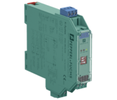
KFD2-STC5-Ex1
Ex-erotin analogiatuloviesteille
- 1-kanavainen galvaaninen erotin
- 24 VDC jännitesyöttö (Power Rail)
- Tulo Hart-viestin läpäisevä, 2-johdinsyöttö
- Lähtö 0/4-20mA, aktiivinen/passiivinen
- Kotelon leveys 20 mm
- SIL 2